This focus idea is explored through:
Contrasting student and scientific views
Student everyday experiences
 It is not surprising that students have confused meanings for words used to talk about electricity. When scientists were first trying to understand electric circuits, they used words already in our language for the concepts they were constructing in their explanations, e.g. ‘current’, ‘power’. But of course, the meanings for these words, when the scientists used them, were different from the everyday meanings that already existed. Later, the words scientists created for concepts like ‘voltage’ moved slowly into everyday language and acquired meanings in our everyday talk different from the precise meanings used by scientists. So, as described in both
Electric circuits and
Making sense of voltage, the differences between meanings for words in everyday use and their scientific use are very often a source of considerable conceptual confusion for students when they are learning about electricity.
It is not surprising that students have confused meanings for words used to talk about electricity. When scientists were first trying to understand electric circuits, they used words already in our language for the concepts they were constructing in their explanations, e.g. ‘current’, ‘power’. But of course, the meanings for these words, when the scientists used them, were different from the everyday meanings that already existed. Later, the words scientists created for concepts like ‘voltage’ moved slowly into everyday language and acquired meanings in our everyday talk different from the precise meanings used by scientists. So, as described in both
Electric circuits and
Making sense of voltage, the differences between meanings for words in everyday use and their scientific use are very often a source of considerable conceptual confusion for students when they are learning about electricity.
The focus idea
Introducing scientific language also explores issues of everyday and scientific language use.
In terms of language, the scientific idea of ‘electrical resistance’ is a somewhat different case, for two broad reasons.
Firstly, it is almost unknown for students to think about ‘electrical resistance’ before some form of this idea is formally introduced to them. In the uncommon cases where students do use some notion they call ‘resistance’ to interpret everyday experiences, this will almost always be together with them thinking about ‘electrical current’ (and/or very occasionally some notion of ‘voltage’).
Secondly, if they do have a notion of resistance, it is usually broadly consistent with the acceptable scientific view – a notion of ‘resistance’ involving a form of ‘friction’ that somehow impacts on ‘current’.
Some students try to interpret their limited experiences with electric circuits in terms of electrical current only. These students interpret a high current in a circuit as meaning that ‘current flows easily’ through the circuit rather than ‘the electrical resistance is low’ or considering in any way the effects of the voltage across the circuit.
Another issue (described in the focus idea
Electric circuits) that is also significant for student understandings of electrical resistance is what is often described as ‘local reasoning’. That is, their thinking about what is happening in an electric circuit (with matters of electrical resistance as well as current) is often focused on just one small part of the circuit while completely ignoring all other features of the circuit.
Students also often think that if a change is made to one part of an electric circuit it will take some time for its effect to ‘move around’ the circuit rather than instantly impacting on every component in the circuit.
Research: Choi, Lee & Kwon (2004), Cohen, Eylon & Ganiel (1983), Liégeois & Mullet (2002), Reiner, Slotte, Chi, & Resnick (2000), Shipstone & Gunstone (1985) and Viard & Khantine-Langlois (2001).
Scientific view
Models play an important part in helping us to understand things we cannot see and so are particularly helpful when trying to make sense of electrical circuits. Models are valued both for their explanatory capacity and their predictive ability. Models however, also have limitations.
The model used by scientists today for electric circuits makes use of the idea that all substances contain electrically charged particles (see the focus idea
Macroscopic versus microscopic properties). According to this model electrical conductors, such as metals, contain charged particles that can be moved from atom to atom relatively easily whereas in poor conductors, insulators, such as ceramics, charged particles are much harder to move.
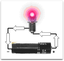
In the scientific model, electric current is the overall movement of charged particles along a continuous conducting pathway. The cause of this movement is usually an energy source like a battery, which provides the force needed to move the charged particles. An electrical current can only occur when there is a complete conducting ‘circuit’ for the charged particles to move away from one terminal of the battery and towards the other, (see
Electric circuits) as shown by the arrows indicating the conducting path in the diagram below.
 Charged particles can pass relatively easily through materials that are good conductors; relatively little electrical energy is needed to create this movement of charge (current) in such materials. On the other hand, insulators require considerable amounts of electrical energy to produce similar currents. The property of materials that results in the difference in energy needed to establish similar electrical currents is called ‘electrical resistance’ and is measured in a unit called the Ohm. The electrical resistance of different materials can vary enormously; the resistance of the most widely used conducting materials (metals) alters with changes in their temperature.
The scientific model of electrical resistance is of the moving charged particles colliding with the particles which comprise the structure of the material through which the current is passing. An energy input is needed to maintain the current because energy is continuously being transformed into heat during these particle collisions. Where the nature of the material is such that collisions are much more frequent, then a greater amount of heat is produced and the electrical resistance is higher.
There are some electrical devices whose functioning depends on this energy transformation, most obviously fan heaters and light globes (where the filament of the globe needs to become white hot so that light as well as heat results from the energy transformation). For these devices we need material with a ‘medium’ electrical resistance - low enough that an appropriately sized electric current passes through the material and high enough that appropriate amounts of energy are changed to the form needed. When we connect such devices into electric circuits we seek to have as little energy conversion as possible (as low a resistance as possible) in the wires through which the current passes to and back from the device, and an extremely high resistance for materials such as the plastic insulation around the conducting wires that are intended to not have current pass through them.
The ‘colliding particles’ or mechanical model of resistance described above is useful when considering currents in simple conductors. It is not helpful in trying to explain the much more complicated functioning of currents in fluorescent lights, light emitting diodes (LEDs) and many complex electronic components. All models/metaphors/analogies have their limitations. For the mechanical model, the most obvious limitation is that it assumes that all particles are essentially identical and behave in the same way as tiny ball bearings or marbles.
Critical teaching ideas
- The concepts of electrical resistance and electrical current are closely intertwined and need to be taught at the same time.
- Electrical resistance is the property of materials that results in energy being required to maintain an electric current in the material. All materials we encounter in everyday contexts have an electrical resistance; this resistance can vary enormously.
- Different materials require different amounts of energy to achieve equivalent current flows. Materials that require very little energy to enable a current to flow are called conductors; these have very low electrical resistance. Materials that require a great deal of energy to enable current flow are called insulators; these have very high electrical resistance.
In designing electric circuits to enable us to use electrical devices to transform electrical energy we need:
- materials with electrical resistance as low as possible for conducting wires
- materials with electrical resistance as high as possible for parts of the circuit where electrical insulation is needed
- materials with electrical resistance that is neither very low nor very high for the energy converting parts of the device the circuit is designed for.
The suggestions in this focus idea have been written in ways that assume that the concept of ‘electric current’ has been introduced first (see
Electric circuits), Additional concepts and suggestions are then closely intertwined with these ideas.
As with both
Electric circuits and
Making sense of voltage, it is very important to note that the use of quantitative approaches to teach these ideas (e.g. using Ohm’s Law) will often impede the development of conceptual understanding and the development of the ability to explain electrical phenomena.
This is because when the focus is on using the formula that represents Ohm’s Law (V=IR), the nature of student learning is quite disconnected from any of the concepts that the terms in the formula are representing. An approach that is much more likely to promote student understanding is a qualitative approach, one focused by the use of broad questions like:
- What are the central concepts here?
- How can these concepts be used to explain some simple electrical phenomena?
- What is the appropriate descriptive account of how the concepts are related?
 Explore the relationships between ideas about electrical current, resistance and voltage in the
Concept Development Maps – Electricity and Magnetism
Explore the relationships between ideas about electrical current, resistance and voltage in the
Concept Development Maps – Electricity and Magnetism
Teaching activities
Collecting evidence/data for analysis
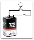
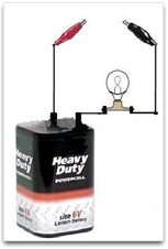 Provide a range of prepared materials for students to measure electrical resistance using a bulb, battery and connected test leads as shown here. These items should be selected to provide two distinct groups of items for students to explore: either very good insulators or very good conductors. The intention is for students to test each material using their bulb and battery to establish if the bulb does or does not light (i.e. draw conclusions that the material is a good conductor or good insulator). The objective is for students to see that most metals are very good conductors and that plastic and ceramics are used widely in the design of electrical hand tools because of their very good insulation properties.
These items could include: wood, ceramic, plastic, polystyrene, rubber, paper, glass, copper wire, aluminium foil, iron/steel nails, carbon/graphite rods*, brass keys and zinc flashing.
*Graphite rods can be obtained by sharpening a black lead pencil at both ends and using alligator clips to connect it into the circuit (what we call the ‘lead’ in a black pencil is in fact graphite).
Discuss with students why materials are selected for their insulation properties. Questions for discussion could include:
- Why should electricians use wooden or fiberglass ladders and not aluminium ladders?
- Why are conducting wires coated with insulating plastic?
- How will designing electrical hand tools and hair dryers with plastic molded cases avoid electric shock during possible malfunction?
An alternative approach to this task is outlined in the vignette,
Deduce the practical design from limited information which advocates using less teacher direction, encouraging students to exercise greater decision making.
Open discussion via a shared experience
Select a second group of conductors to provide a range of electrical resistances from high to low for the students to test again with a battery, bulb and test wires (i.e. the test bulb brightness will vary from dim to bright). The intention is to provide students with the more difficult task of comparing the relative resistances of each material so they can rank them from poor to very good conductors. These items should be selected with care so they have the required resistance for the bulb to vary in brightness and are appropriate for the battery voltage used. Be sure to trial each before giving them to your students to test.
These items could include lengths of: solder, lead foil, nichrome (including different pieces of nichrome wire of vastly different lengths; a bar radiator coil is an excellent source) and copper wire.
Have the students test each sample and attempt to rank them on a continuum from high resistance (poor conductor, dim bulb) to low resistance (good conductor, bright bulb).
Practice using and building the perceived usefulness of scientific models
Construct a simple physical simulation like the one below or use one of the many computer simulations (such as those provided on the Interactive Simulations website below) to assist students to build an understanding of the ‘particle collision’ model of electrical resistance.
A simple physical simulation could consist of a table tennis ball rolling down a slightly inclined table with a number of obstructions (e.g. 50g brass weights) positioned to retard the ball’s movement. Restrict the ball’s sideways path by placing some objects on each side of the table. (e.g. metre rulers raised on several weights at each end).
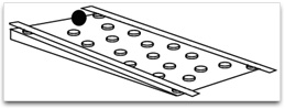 The speed of the ball down the slope can be altered by changing the number of obstructive weights in the ball’s path or the slope of the table. The additional placement of more weights will increase the number of deflective collisions encountered by the ball and hence slow the ball’s progress as it rolls down the incline. The increased number of collisions models a material with high resistance and low conductivity. After demonstrating and discussing this simulation with students have them prepare a list of the model’s assumptions, predictive powers and shortcomings. Their ideas could then be presented using an information table like the one below that lists the strengths and weaknesses of the simple mechanical simulation in accurately modeling electrical resistance.
| Mechanical Model - Strengths | Mechanical Model - Weaknesses |
|---|
The movement of the ball is like the flow of electric current through the conductor. |
The ball and weights do not ‘heat up’ more when greater numbers of ‘particle collisions’ occur. |
The greater the number of ‘particle collisions’ the slower the current (‘the ball’) moves through the conductor. |
The relative sizes of the particles are all wrong. |
We can give the moving ball more energy and hence speed up its motion by increasing the slope of the table. |
If there are really large numbers of obstructing weights the rolling ball might get stuck and not be able to move. In an electric current, the speed of the moving particles is broadly constant; changes in currents involve changes in the number of moving particles, not the speed at which they move. |
As an extension activity, have students work in small groups to prepare poster-sized diagrams that attempt to provide further insights into the operation of the ‘particle collision’ model. Encourage students to discuss and draw features identified in their strengths and weaknesses table which will influence the effectiveness of the model, e.g. the relative size of the moving particles compared with the stationary particles, changes in the number of moving particles, changes in the dimensions of the pathway’s length or cross-section. Have students present these to their peers in small groups for discussion.
For another task which also discusses the use of analogies with the concepts of electrical circuits see the vignette
Using Logbooks in Year 10 Electricity.
Promote reflection on and clarification of existing ideas
Using the structure of a POE (Predict, Observe, Explain), have students in groups of 2-3 (or more if there is insufficient equipment):
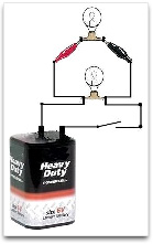
a) Connect up an electric circuit containing a battery, a light globe and a switch so there is only one single path for the current in the circuit. This is called a series circuit. Have students observe the globe lit when the switch is closed. |
|
b) Generate a single group prediction about what will happen to the brightness of the globe (in qualitative ways – increase, decrease, stay the same) when a second globe is connected up also in series with the other components, one after the other. |
|
c) Agree on and record an observation of what happens to the brightness of the globe when the second globe is connected into the circuit. |
d) Write a single, group explanation of their observation. |
Now discuss with the class the model of resistance as arising from collisions between moving charges and the particles in the wires through which the current moves (i.e. the ‘particle collision’ model of electrical resistance). How will the introduction of a second bulb influence the current flow and brightness of the first bulb?
Have students in their original groups rewrite their original POE explanations so that these are now in terms of this particle model of resistance.
Helping students work out some of the ‘scientific’ explanations for themselves
Have students connect again the original circuit of a battery and single light globe and switch.
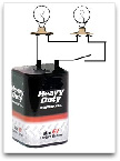
Have students observe and record what happens to the brightness of the globe when a range of different materials are connected (one at a time) in a way that means the current has two possible paths – either through the globe or through the other object that is being added (this is called a parallel circuit).
For example, the diagram shows a second light bulb connected to the circuit using alligator clips.
 Suggestions for a range of materials:
- another light globe as shown in the diagram above
- a short piece of copper wire (which can only be part of the circuit with the switch closed for a very short time!)
- a very long coil of wire (that is designed to add resistance to an electric circuit)
- the graphite in a pencil (as noted, sharpen the pencil at both ends and use alligator clips to connect the pencil into the circuit)
For each material have students generate a group explanation of their observations of what happens to the brightness of the globe when the material is added, in terms of the particle model of resistance.
Consolidate student ideas via a whole class discussion of the range of explanations produced.
Provide an open problem to be explored via play or through problem solving
As a library/internet research assignment, have students explore the nature and use of superconductors via the structure of the teaching procedure, called
What? So what? What next? This involves students researching possible answers to the following questions:
-
What? – What facts can students find in response to the question ‘What are superconductors and what do they do?’
-
So what? – For each fact students produce in response to ‘What?’ they should write as many consequences of this fact as they can; a series of responses to the question ‘So what?’
-
What next? – For each fact given for ‘What?’ and consequence given for ‘So what?’ students write what might result or happen as a result of this.
Have students set out their responses in a table such as this:
| WHAT? | SO WHAT? | WHAT NEXT? |
|---|
What are superconductors and what do they do? | What is a consequence of this? | What might happen as a result of this? |
Superconductors are materials that, when cold enough, conduct an electric current without any resistance. |
Once a current is started in a superconductor with no resistance, this current will keep flowing forever without any energy input. |
An electric current could be stored just by starting the current in a superconductor and then leaving it. |